07/07/2016
Today was an interesting day for me as I started off with nearly all 0's on my minimum competencies sheet.
We began with very simple circuits using a battery pack, an LED, a resistor and a simple switch. This was useful as to begin with I just attached them without much care then had to look more closely at the diagram to realise that the LED's legs were positive and negative and had to go a certain way to work.

We then moved on to looking at Current (I), Voltage (V) and Resistance (R) and how to calculate each one. This involved using a MULTIMETER and it's various functions. To do this, we re-created our circuit using breadboards. These boards are the same as a circuit board with a negative side, 2 central columns and then a positive side. The 4 columns need to be joined in some way for it to create a full circuit. The components also have to have their own legs on different rows but with 1 leg on the same row as the previous element and the one after.


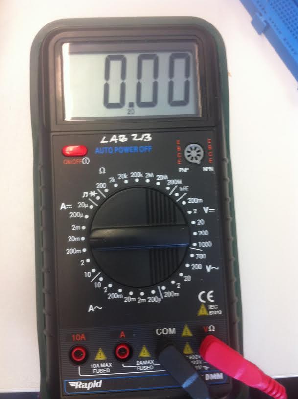
When using the MULTIMETER, you need to set it to the correct reading e.g. Alternating current (sockets at home - the one with the sin symbol after the A) AC or Direct Current (batteries - the one with the = symbol but with 3 dots instead of a line underneath) DC for CURRENT. Then the same but with V for voltage and then Ω for Resistance. The number then needs to be set to the setting that is closest but higher than your reading.
ALSO ENSURE THE RED LEAD IS IN THE CORRECT SOCKET AT THE BOTTOM.
I also learnt that current stays the same the whole way round the circuit but volts run out by the time they get to the battery.
OHMS' LAW
Ohms' Law is very simple:
V = I x R
R = V ÷ I
I = V ÷ R

RESISTOR COLOUR CODES
Once you have worked out the resistance, you need to pick an appropriate resistor. This is easily worked out using the table below:

For example:
Colour code for 270Ω is Red (2), Violet (7), Brown (0) then silver for a 10% tolerance.
CIRCUIT WIZARD
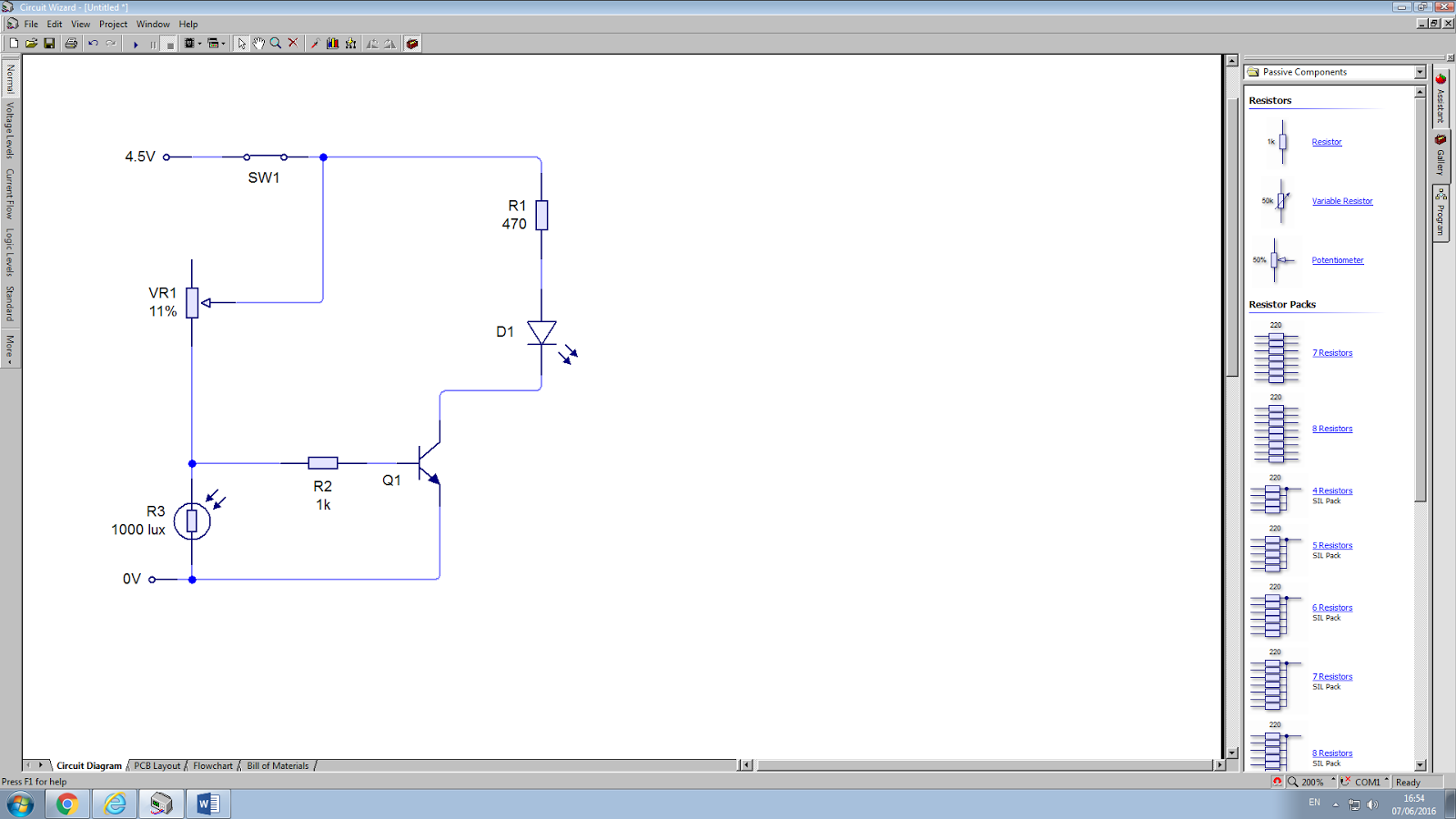
This afternoon we had a go at using the Circuit Wizard. This programme is brilliant for testing ideas for circuits very quickly, allowing you to get a grasp of the basics of electronics. I tried to do a more complex circuit with a bulb and LED which were independent of each other. This was a bit tricky but the software helped me work it out reasonably quickly.
We then went on to create a circuit featuring a Light Dependant resistor. This meant that the LED came on when it went dark. From this, we used copper tape and a soldering iron to create this circuit in real life.
I really enjoyed this hands on activity.
USEFUL RESOURCES:
Kitronik - www.kitronik.co.uk
Rapid Electronics - www.rapidonline.com
Adafruit - www.adafruit.com
Spark Fun www.sparkfun.com
Cool Components www.coolcomponents.co.uk
No comments:
Post a Comment